How to Lay Track on a T-Trak Module
This is a presentation of how I lay track on a T-Trak module. I researched the primary method which consists of a series of drilling, tapping and securing the track. This seemed much too difficult and time consuming for my purposes so I decided on my own method of laying track.
I simply line up the track and hot glue it down. At first, I was leery as to how secure this method would be until I had to take up some track. This proved to be much more difficult than I had expected. The result was that I was more than satisfied about the security of the track.
Don't be fooled by the process. Laying the track should take no more than 15 minutes from beginning to end.
This hobby is earmarked by everyone having their own method of doing things. I am simply presenting a the method that works for me. Hopefully, someone...somewhere will find this information helpful.
Enjoy.
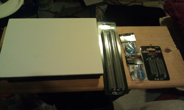
A T-Trak standard straight module. In this case, a converted Clementine crate.
2 pieces of Kato 9 3/4" straight track (20-000).
2 pieces of Kato 2 7/16" straight track (20-040).
2 pieces of Kato Terminal Unijoiners (24-818).
Hot glue gun with glue.
Drill with 7/16" paddle drill bit.
Kato rail-it.
Red electrical tape.
Yellow electrical tape.
Tie wrap sticky back base.
Tie wrap.
We start off with organizing the things we will need to lay the track.
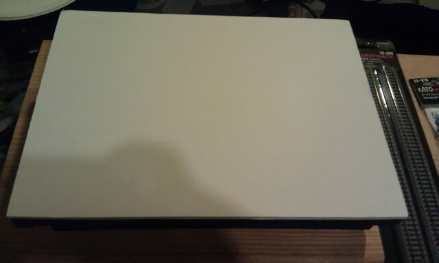
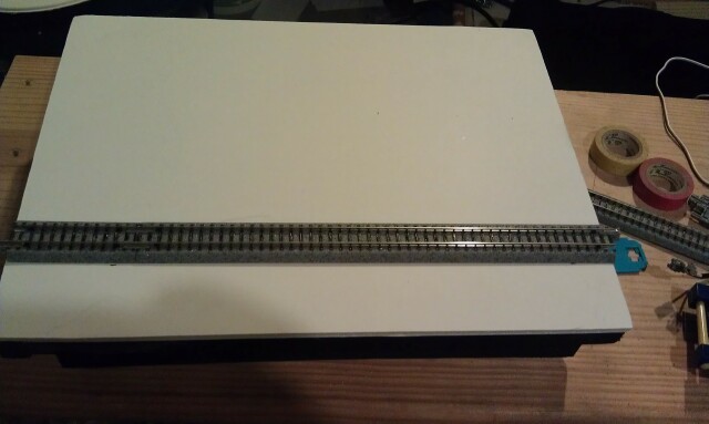
This is the module that will receive the track.
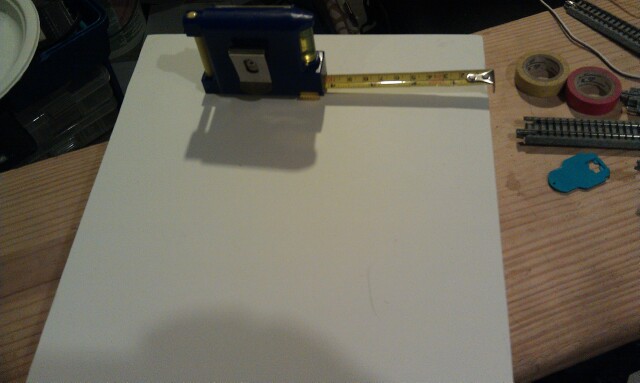
First, we decide which side will be the front of the module. Once this is done, we place a tick mark at both ends of the module that is 1 1/2" from the front edge.
We connect a 9 3/4" and a 2 7/16" track together and line the track up on the tick marks. Once the track is perfectly aligned on the tick marks and to the ends of the module, we mark where the track joint is located. We are in the habit of placing the track joint to the left side of the module for the front track and the track joint to the right on the inside track. This helps to prevent crowding of the wiring.
Now we disconnect the track and replace the rail joiners with the terminal joiners. By T-Trak standard, the blue wire goes to the outside of the track for the Red line (outside) track.
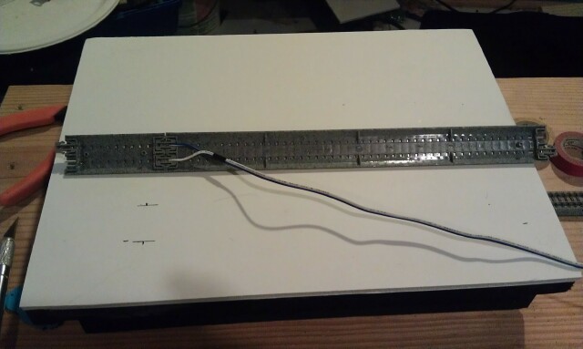
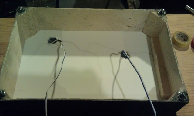
Notice that the feeders are angled towards the middle of the module. Again, this is done to help prevent crowding the wiring. A 7/16" hole is drilled through the foam core top. Also notice that the hole is offset to the right in order to accommodate the angle of the wiring.
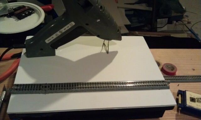
The wire is then run through the hole and the track is roughly in place.
The track is again perfectly aligned with the tick marks and to the ends of the module. The we hot glue both ends in order to tack the track in place. We then run a bead of hot glue along each side of the track applying pressure to the track until the glue sets up (about 5-10 seconds).
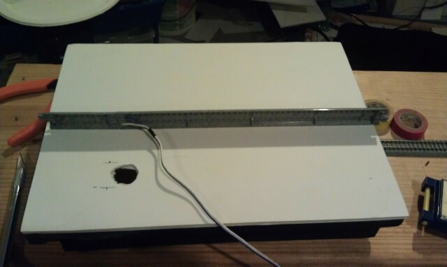
Now that the outside track is secured, we can begin to work on the inside track. We will need the Kato rail-it as it also has the parallel track gage on it. We connect a 9 3/4" and a 2 7/16" track together. We locate the rail joint to the right side of the module. When the track is perfectly aligned, using the rail-it for alignment with the outside track and with the ends of the module, we mark the rail joint.
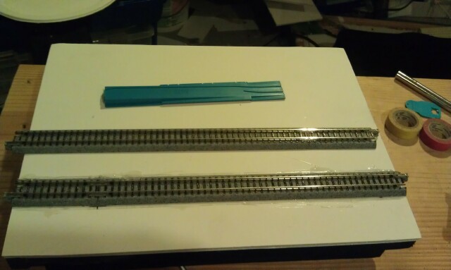
We then disconnect the two pieces of track and replace the rail joiners with terminal joiners. Notice that the feeder wires are angled towards the middle of the module. This is done in order to prevent the wiring from crowding.
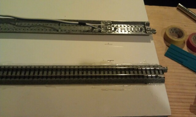
A 7/16" hole is drilled into the foam core top. Notice that the hole is offset to the left in order to accommodate the angle of the wiring.
Once completed, we run the wire through the hole and place the track into place. Once the track is perfectly aligned, we hot glue it into place using the same method as the outside track.
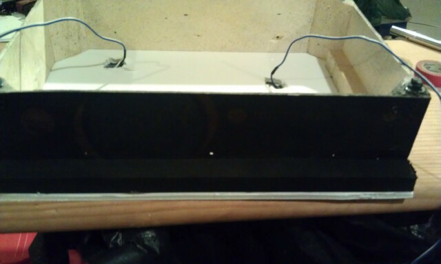
We then flip the module upside down to expose the under module wiring.
We are now ready to drill a 7/16" hole into the side of the module. The hole is drilled into the back side of the module...not the front side.
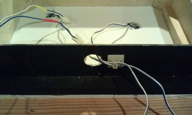
The wires are routed through the hole we drilled. We add a sticky backed tie wrap base to the outside of the module. We then tie wrap the wires in order to provide some strain relief. Also notice that the wire that is connected to the outside track has red tape applied to the connection end of the wire and the wire that is connected to the inside track has yellow tape applied to the connection end of the wire. This is done in order to make identifying which wire goes to which track.
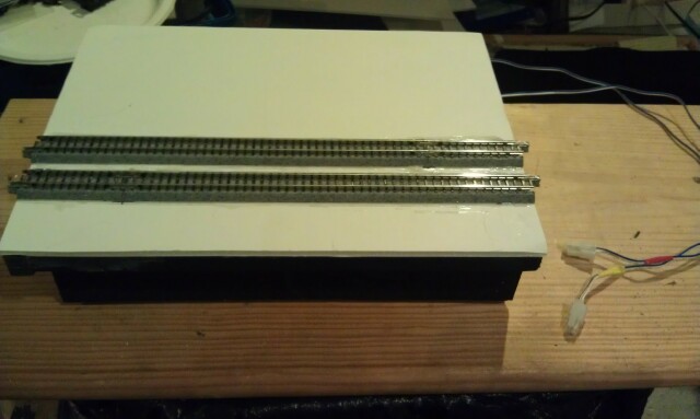
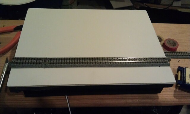
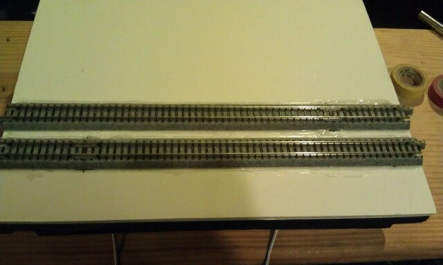
The finished product. The module is now ready for scenery.
This is the process that I use for laying track on a T-Trak module. It takes much longer to describe the process than to actually perform the process.
The hot glue marks are very easily hidden by the scenery and ballast and does not weaken during the scenery process. I have used this method on straights and corners literally dozens of times and have never experienced a failure or separation.
So, in the vein of keep it simple stupid, this is what I came up with.